

What Solar Roof Mounting System Options Exist for Asphalt Roof Applications?
2026-09-10
1. What Are the Primary Attachment Methods for Asphalt Roof Solar Mounting?
There are three primary attachment methods for mounting solar panels on asphalt shingle roofs: lag bolt with flashing, chemical anchor, and adhesive mounting. The lag bolt with flashing is the industry standard for pitched roofs. A hole is drilled through the shingle and roof deck, a lag bolt is driven into the rafter, and a flashing piece is slid under the shingle above the penetration. The flashing directs water away from the hole. Chemical anchors use an adhesive to bond a stud to the roof surface without penetrating the deck. They are less common because they rely on the strength of the adhesive and the shingle bond, which can degrade over time. Adhesive mounting is used for temporary or low-profile installations.
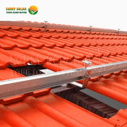
The table below compares these methods.
| Attachment method | Pull-out strength | Waterproofing reliability | Installation speed | Typical application |
| Lag bolt + flashing | High (dependent on rafter) | Excellent (when properly installed) | Moderate | Standard pitched roof installations |
| Chemical anchor | Moderate | Good (no penetration) | Fast | Low-profile or temporary mounts |
| Adhesive mounting | Low | Good (no penetration) | Fast | Small panels or non-structural roofs |
In our factory, we manufacture Solar Roof Mounting System components that are designed for the lag bolt and flashing method. Our flashing pieces are made from aluminum or stainless steel and are shaped to fit under the course of shingles above the penetration. We also supply EPDM rubber gaskets that seal around the lag bolt. The combination of mechanical fastening and flashing provides the most reliable waterproofing for asphalt roofs.
2. How Do You Determine the Correct Spacing and Load Distribution for the Mounting System?
The spacing of the mounting attachments determines the load distribution on the roof structure. If the attachments are spaced too far apart, the rails may deflect under wind or snow load. If they are spaced too closely, the number of penetrations increases, which increases the risk of leaks. The correct spacing is determined by the structural capacity of the rafters, the span of the rails, and the design loads. The table below shows the recommended attachment spacing for different rail spans and design loads.
| Rail span (mm) | Design wind load (Pa) | Design snow load (Pa) | Recommended attachment spacing (mm) | Maximum rafter spacing (mm) |
| 1200 | 1200 | 1000 | 800 | 600 |
| 1500 | 1200 | 1000 | 1000 | 600 |
| 1800 | 1200 | 1000 | 1200 | 600 |
| 1200 | 2400 | 2000 | 600 | 600 |
| 1500 | 2400 | 2000 | 800 | 600 |
The rafter spacing is a critical factor. If the rafters are spaced at 600 mm centers, the attachments must align with the rafters. If the rafters are spaced at 900 mm or more, additional blocking may be required between the rafters to provide a solid mounting point. Our Solar Roof Mounting System includes rails that are available in different thicknesses to accommodate different spans. We also provide engineering support to help installers calculate the correct spacing for their specific project.
3. What Waterproofing Details Are Critical for Long-Term Performance?
The waterproofing of a Solar Roof Mounting System on an asphalt roof depends on three details: the flashing, the sealant, and the fastener. The flashing must extend at least 100 mm under the shingle course above the penetration and at least 50 mm on each side. The sealant must be a high-quality polyurethane or silicone that remains flexible over the temperature range. The fastener must be a lag bolt with a neoprene or EPDM washer that compresses against the flashing. In our factory, we test our flashing and gasket assemblies in a rain simulator that applies water at a rate of 100 mm per hour for 24 hours. We also test the assemblies under thermal cycling from -20°C to +80°C to verify that the sealant and gasket maintain their properties.
Common installation error: Placing the flashing over the shingle instead of under it. The flashing must be installed under the shingle course above the penetration, so that water flows over the flashing and onto the shingle below, not under it. This is the single most important waterproofing detail.
4. How Does the Choice of Rail and Clamp Affect Installation Efficiency?
The rail and clamp components of a Solar Roof Mounting System affect both the structural performance and the installation time. The rail profile determines the stiffness and the ease of attaching the panel clamps. The clamp design determines how quickly the panels can be secured. In our factory, we manufacture rails with a grooved profile that allows the clamps to be positioned anywhere along the rail without drilling. This reduces installation time by approximately 30 percent compared to systems that require pre-drilled holes. Our clamps are designed with a single bolt that secures both the panel frame and the rail connection. We also offer a grounding clip that eliminates the need for a separate grounding wire, which further reduces installation time.
Frequently Asked Questions About Solar Roof Mounting Systems for Asphalt Roofs
Summary for Solar Installers
The selection of a Solar Roof Mounting System for asphalt roof applications requires careful consideration of the attachment method, the load distribution, the waterproofing details, and the installation efficiency. The lag bolt with flashing method remains the most reliable for pitched roofs. The spacing of the attachments must be determined by the structural capacity of the roof and the design loads. The waterproofing details, particularly the flashing placement, determine the long-term performance of the installation. Our factory has been manufacturing Solar Roof Mounting System components for over 12 years and supplies to installers across North America, Europe, and Australia.
Xiamen Egret Solar New Energy Technology Co., Ltd. manufactures a complete range of Solar Roof Mounting System components for asphalt roof applications, including flashed attachments, rails, clamps, and grounding clips. We provide engineering support, load tables, and installation guides.