

What Makes an Intelligent Tracker Communication Box Protect Power Systems?
2026-10-28
A utility engineer is reviewing a fault event at a 20 megawatt distributed photovoltaic site. A feeder fault occurred, and the protection relay at the substation should have isolated the faulted feeder within 100 milliseconds. The relay operated, but the fault current continued to flow for nearly 400 milliseconds because the communication path between the tracker controllers and the substation was congested with data traffic. The delay was not caused by the relay. It was caused by the communication architecture. This is why a dedicated Intelligent Tracker Communication Box is used at each node of a distributed power system. The box separates the protection data path from the monitoring data path, so that a network congestion does not delay a protection action. This guide explains what makes the communication box a protection asset.
1. Why Does a Distributed Power System Need a Dedicated Communication Layer at Every Node?
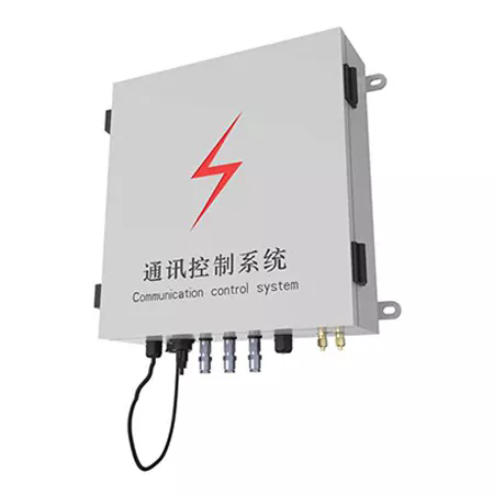
A distributed power system includes hundreds of inverters, tracker controllers, combiner boxes, and transformers spread over a large site. The monitoring data from these devices is sent to a central control room for performance analysis and reporting. The protection signals, however, must travel in the opposite direction with a much shorter latency. If the same communication channel carries both the monitoring data and the protection signals, a burst of monitoring traffic can delay the protection signal. The Intelligent Tracker Communication Box solves this by providing two separate data paths. One path carries the monitoring data to the control room. The other path carries the protection and control signals with priority and deterministic timing. In our factory, we design the communication box with dual-channel architecture and hardware-based priority. Suzhou Ruitai Automation Technology Co., Ltd. has been manufacturing communication boxes for over 10 years.
The dedicated layer at each node also reduces the cabling cost. A single fiber or Ethernet backbone connects the boxes in a ring, and each box connects to the local devices through short serial or Modbus links. The ring topology provides redundancy: if one fiber segment is cut, the data can travel the other way around the ring, and the protection function continues without interruption.
2. How Does the Box Collect and Transmit Data Without Interrupting the Protection Function?
The communication box has two internal sections. The collection section reads data from the local devices through Modbus RTU, Modbus TCP, or IEC 61850. The protection section monitors the local voltage, current, and status signals and executes the local protection logic. The two sections are electrically isolated but share the same power supply and enclosure. The collection section can be busy with a large data upload without affecting the timing of the protection section. The table below shows the technical parameters of the two sections.
| Parameter | Collection section | Protection section |
| Scan cycle | 100 – 1,000 ms | 1 – 10 ms |
| Protocol | Modbus TCP, IEC 61850, MQTT | Hardwired, GOOSE, proprietary priority channel |
| Communication interface | 2 x Ethernet, 4 x RS485 | 2 x fiber, 2 x dry contact |
| Isolation voltage | 1,500 V AC | 2,500 V AC |
| Power consumption | 12 W | 8 W |
In our factory, we test the isolation between the two sections at 2,500 V AC for one minute. We also test the protection response time with the collection section running at full data load. The protection response time remains within 10 milliseconds in all test cases. Suzhou Ruitai Automation Technology Co., Ltd. provides the test report with each shipment.
3. What Role Does Edge Computing Play in Reducing Response Time?
Edge computing means that the data is processed at the communication box, not at the central control room. The box runs a local logic engine that evaluates the measured values against thresholds and executes the local action if a threshold is exceeded. The local action may be a trip command to the inverter, a curtailment command to the tracker, or an alarm to the control room. The advantage is that the response time does not depend on the network latency or on the control room availability. If the network is down, the local protection continues to operate. The table below compares local processing with cloud processing for a typical protection event.
| Parameter | Local edge processing | Cloud processing |
| Response time | 10 – 50 ms | 200 – 2,000 ms |
| Dependency on network | None | Required |
| Bandwidth usage | Low (only events and summaries) | High (raw data) |
| Operation during network outage | Continues | Stops |
| Data storage | Local buffer, 30 days | Cloud, unlimited |
Power system engineer's note: The edge computing capability is what makes the Intelligent Tracker Communication Box a protection device rather than a data gateway. The local logic engine must be deterministic, meaning that the response time is bounded and predictable. We implement the logic engine on a real-time operating system with a fixed scheduling cycle. Suzhou Ruitai Automation Technology Co., Ltd. provides the logic configuration tool and the response time test report with each box.
4. Why Do Isolation and Surge Protection Determine the Box's Reliability in Harsh Environments?
A communication box installed in a photovoltaic or storage site is exposed to surges from lightning, switching operations, and static discharge. The surge can enter through the power supply, the Ethernet cable, or the RS485 cable. If the box is not protected, the surge can damage the communication interface or the processor, and the protection function is lost. The box must have three levels of protection. The first is galvanic isolation on every communication port. The second is a surge protection device on the power supply and on the communication lines. The third is a robust enclosure with proper grounding. In our factory, we test every port with a 6 kV surge pulse according to IEC 61000-4-5. The box must continue to operate after the test. We also test the isolation at 2,500 V AC. Suzhou Ruitai Automation Technology Co., Ltd. uses a metal enclosure with a dedicated grounding terminal to ensure a low-impedance path for the surge current.
We also recommend that the installer use shielded twisted-pair cable for the RS485 links and fiber optic cable for the backbone. Fiber optic cable is immune to electromagnetic surges and provides a natural isolation between the nodes.
5. How Should Engineers Specify and Verify an Intelligent Tracker Communication Box?
The specification should include six items. The first is the communication protocol and the number of ports. The second is the isolation voltage for each port. The third is the surge immunity level. The fourth is the operating temperature range. The fifth is the enclosure protection rating. The sixth is the local logic capability, including the number of logic rules and the response time. The verification should include four tests. The first is a protocol conformance test with the actual devices. The second is an isolation withstand test. The third is a surge immunity test. The fourth is a high and low temperature operating test. In our factory, we perform these tests on a sample basis for each production lot and provide the test report with the shipment. Suzhou Ruitai Automation Technology Co., Ltd. also offers a factory acceptance test with the customer's devices connected.
We recommend that the designer verify the response time of the local logic under the maximum communication load. A box that meets the response time specification at no load may fail at full load if the processor is shared between the collection and the protection tasks.
Frequently Asked Questions About Intelligent Tracker Communication Boxes
Summary for Power System Engineers
The Intelligent Tracker Communication Box protects power systems by separating the protection data path from the monitoring data path, by running the protection logic locally at the edge, and by providing isolation and surge protection on every port. These features ensure that the protection action is not delayed by network congestion and that the box continues to operate in harsh electrical environments. The specification should include the protocol, the isolation voltage, the surge immunity level, the temperature range, the enclosure rating, and the local logic capability. The verification should include protocol conformance, isolation withstand, surge immunity, and temperature testing. Suzhou Ruitai Automation Technology Co., Ltd. has been manufacturing communication boxes for over 10 years and provides full specification and verification support for power system projects.