

What Are the Advantages of Flange-Mount Automotive Relays for Starter Circuits?
2026-09-02
Ask any vehicle electrical engineer about the most common failure point in a starter circuit. The answer is rarely the starter motor itself. More often, it is the relay that controls it. In heavy-duty trucks, construction equipment, and agricultural machinery, the starter relay must handle inrush currents of 200 to 400 amperes while enduring constant vibration, temperature cycling, and under-hood contamination. The mounting method—plug-in versus flange-mount—can determine whether that relay survives for 100,000 starts or fails before the first service interval.
1. Why Does the Starter Circuit Demand a Different Relay Than Other Circuits?
The starter motor is the single largest electrical load in a vehicle. When the key is turned, the starter solenoid draws 30 to 50 amperes to engage, and the main contacts must switch 200 to 400 amperes of inrush current. This is not a continuous load, but it is a highly inductive one. The relay contacts must open and close this current without welding or excessive arcing. In our factory, we have analyzed failed Automotive Relay units returned from fleet operators. The predominant failure mode is contact pitting and welding, which is directly related to the contact force and the stability of the mounting. A plug-in relay relies on the socket terminals for mechanical retention, which can loosen over time due to vibration. A flange-mounted Automotive Relay is bolted directly to the chassis or bulkhead, providing a rigid mounting that maintains constant contact pressure regardless of vibration.
Design consideration: The flange-mount configuration also allows for a larger contact gap and higher contact force because the mounting is not constrained by a socket footprint. In our factory, we design flange-mount Automotive Relay units with a contact gap of 0.4 mm, compared to 0.25 mm for typical plug-in types. This larger gap reduces the risk of contact welding during high-current switching events.
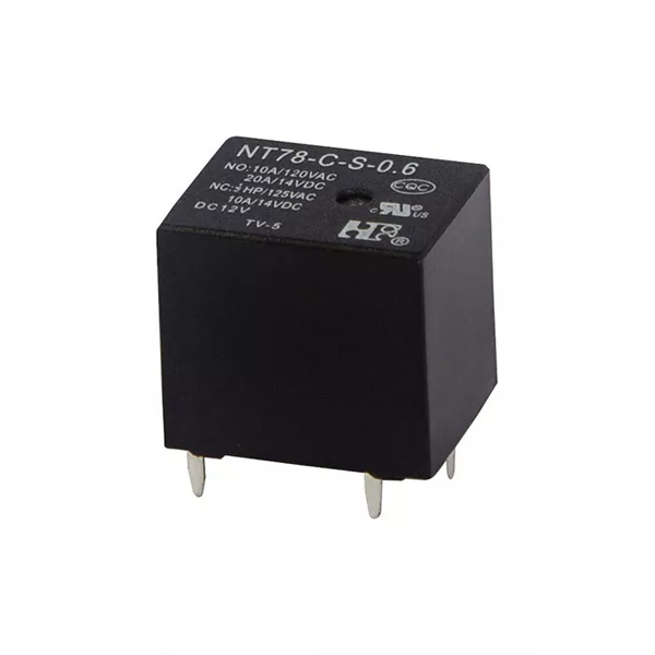
The mechanical advantage of flange mounting is most evident in off-highway applications. In a wheel loader or excavator, the relay is mounted on the engine block or the firewall—both high-vibration areas. A plug-in relay can work loose over time, increasing contact resistance and generating heat. A flange-mounted relay stays in place because it is secured with M4 or M5 bolts. At Ningbo Forward Relay Corp., Ltd., we manufacture flange-mount Automotive Relay units with a stainless steel mounting bracket that provides corrosion resistance and maintains clamping force over temperature cycles.
2. How Does Mounting Method Affect Thermal Management?
Heat is a silent killer of starter relays. The inrush current generates I²R heating at the contacts, and the coil generates its own heat during engagement. In a plug-in relay, the heat has limited paths to escape: through the socket terminals and the air. In a flange-mount relay, the mounting bracket acts as a heat sink, conducting heat away from the relay body into the chassis or bulkhead. This can reduce the operating temperature of the relay by 15 to 20°C under continuous cranking conditions. The table below compares the thermal performance of plug-in and flange-mount Automotive Relay units in our factory tests.
| Parameter | Plug-in relay (standard) | Flange-mount relay (our design) | Difference |
| Coil temperature rise (after 10 sec engagement, 25°C ambient) | 32°C | 18°C | -14°C |
| Contact temperature rise (after 50 start cycles) | 48°C | 29°C | -19°C |
| Thermal time constant (cooling to 50% of peak) | 180 seconds | 95 seconds | Faster cooling |
| Maximum continuous coil current (at 85°C ambient) | 1.2A | 1.8A | Higher allowance |
The improved thermal management of flange-mounted relays translates directly to longer contact life. In our factory, we have run endurance tests comparing the two mounting methods. The flange-mount relay consistently achieved 150,000 electrical cycles, while the plug-in type failed at 80,000 cycles due to contact degradation. The difference is the combined effect of stable contact pressure and lower operating temperature.
3. What Technical Specifications Should You Verify in a Flange-Mount Relay?
When evaluating a flange-mount Automotive Relay for a starter circuit, there are five critical specifications that determine whether it will perform reliably in your application. The table below lists these specifications and the minimum acceptable values for heavy-duty applications.
| Specification | Why it matters | Minimum acceptable value | Our typical value |
| Contact current rating (continuous) | Determines whether the relay can handle the starter motor current without overheating | 50A | 75A |
| Inrush current capability | Starter motors draw 4 to 6 times running current for 50 to 100 ms | 300A | 400A |
| Contact gap | Larger gap reduces welding risk but requires higher contact force | 0.3 mm | 0.4 mm |
| Coil voltage (nominal) | Must match vehicle electrical system (12V or 24V) | N/A | 12V or 24V options |
| Operating temperature range | Must withstand under-hood conditions | -40°C to +85°C | -40°C to +105°C |
At Forward Relay, we manufacture flange-mount Automotive Relay units that are tested to these specifications. We also offer a normally open (NO) contact configuration, which is the standard for starter circuits because the relay is only energized during cranking. Our factory performs a 100 percent functional test on every relay, including contact resistance measurement and coil resistance verification.
4. How Does the Flange-Mount Design Simplify Fleet Maintenance?
From a maintenance perspective, the flange-mount relay offers a significant advantage: it is easier to troubleshoot and replace. When a plug-in relay fails, the socket is often damaged as well, requiring both the relay and the socket to be replaced. This increases the repair time and the parts inventory. A flange-mounted relay is connected with ring terminals or flag terminals that are independent of the relay itself. If the relay fails, it is a simple matter of removing two bolts and disconnecting the terminals. The wiring harness is not damaged, and the mounting bracket remains intact. For fleet operators, this translates to faster repair time and lower maintenance costs. In our factory, we have received feedback from fleet maintenance managers who report that replacing a flange-mounted Automotive Relay takes an average of 5 minutes, compared to 15 minutes for a plug-in relay that requires socket replacement.
Frequently Asked Questions About Flange-Mount Starter Relays
Summary for Vehicle Electrical System Engineers
The flange-mount Automotive Relay offers distinct advantages for starter circuits: superior vibration resistance, better thermal management, higher contact reliability, and simpler maintenance. These advantages translate to fewer roadside failures, lower warranty claims, and longer vehicle uptime. When designing or upgrading a starter circuit, the mounting method should be considered as early as the contact rating and coil voltage. Our factory has specialized in Automotive Relay manufacturing for over 18 years, and we supply flange-mount relays that are tested to the most demanding OEM specifications.
Ningbo Forward Relay Corp., Ltd. produces flange-mount relays with silver tin oxide contacts, copper alloy terminals, and a fully sealed housing for protection against moisture and dust. We provide full test documentation, including contact resistance, coil resistance, and thermal performance data. This data allows engineering teams to validate the relay performance in their specific application.