

How Does Grounding Work in Solar Roof Mounting Systems for Lightning Protection?
2026-09-15
1. Why Is a Solar Roof Mounting System More Vulnerable to Lightning Than Other Roof Structures?
A Solar Roof Mounting System creates a large, elevated metallic surface that is exposed to the sky. The aluminum rails and module frames are excellent conductors. When a lightning strike occurs, the current seeks the path of least resistance to ground. If the mounting system is not properly bonded to the building's grounding electrode system, the current may travel through the module frames, the DC cables, or the inverter, causing damage. In our factory, we have analyzed the grounding requirements for installations in high-risk lightning areas, such as the coastal regions of Southeast Asia and the mountainous regions of South America. The key finding is that the grounding system must be designed to handle the full lightning current, which can reach 200 kA for a direct strike. The conductors and connections must be sized to carry this current without melting or arcing.
Lightning current characteristics: A typical lightning strike has a peak current of 30 kA to 100 kA, with a rise time of 8 to 10 microseconds. The current waveform is defined by the 8/20 microsecond standard. The grounding system must be able to dissipate this energy without exceeding the withstand voltage of the equipment.
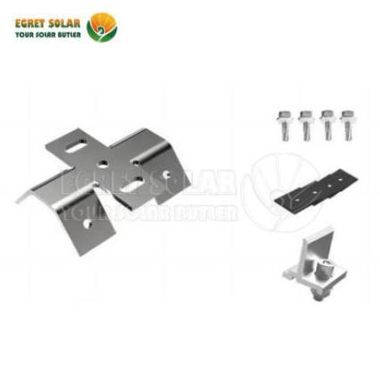
Xiamen Egret Solar New Energy Technology Co., Ltd. designs Solar Roof Mounting System components with integrated grounding paths. Our rails have pre-drilled grounding holes, and our clamps are designed to create a reliable bond between the module frame and the rail without the need for additional jumpers.
2. What Are the Key Components of a Grounding System in a Solar Roof Mounting System?
A complete grounding system for a Solar Roof Mounting System consists of four parts: the equipment grounding conductor, the bonding jumpers, the grounding electrode conductor, and the grounding electrode. The equipment grounding conductor connects the module frames and the mounting rails to the inverter and the combiner box. The bonding jumpers ensure that all metallic parts are at the same potential, eliminating the risk of arcing between them. The grounding electrode conductor connects the system to the grounding electrode. The grounding electrode is typically a copper-bonded ground rod or a concrete-encased electrode (Ufer ground). The table below summarizes the components and their functions.
| Component | Typical material | Function | Key requirement |
| Equipment grounding conductor | Copper or aluminum | Connects frames and rails to inverter | Continuous, low impedance |
| Bonding jumper | Copper, tinned | Connects rail sections and module frames | Listed for grounding and bonding |
| Grounding electrode conductor | Copper | Connects system to ground electrode | Sized for fault current |
| Grounding electrode | Copper-bonded steel rod | Provides contact with earth | Resistance < 25 ohms |
The equipment grounding conductor is the most critical component because it carries the fault current. It must be sized according to the local electrical code. In most cases, a 6 AWG copper conductor is sufficient for a residential system, while a 2/0 AWG conductor is required for a commercial system. The bonding jumpers must be listed for grounding and bonding applications and must be installed with approved connectors.
3. How Does the Grounding Path Differ for Different Roof Types?
The grounding path depends on the roof type and the building construction. The table below shows the typical grounding approach for four common roof types.
| Roof type | Grounding path | Key consideration |
| Concrete flat roof | Grounding conductor routed through conduit to ground rod | Conduit must be UV resistant and watertight |
| Metal standing seam roof | Bonding to the metal roof panel if it is listed as a grounding path | Verify that the roof panel is continuous and listed |
| Asphalt shingle roof | Grounding conductor routed through conduit to ground rod | Conduit must be secured to the roof structure |
| Tile roof | Grounding conductor routed under the tiles to a hidden conduit | Do not drill through tiles; use tile hooks |
For metal roofs, the roof panel itself can serve as the grounding path if it is listed for that purpose. However, the continuity of the path must be verified. If the panels are connected with non-conductive gaskets, a separate bonding jumper is required. In our factory, we provide Solar Roof Mounting System components that are compatible with all of these roof types. Our clamps and brackets are designed to maintain the grounding path even when the roof surface is uneven.
4. How Do You Verify That the Grounding System Meets Lightning Protection Standards?
After installation, the grounding system must be tested to verify that it meets the requirements. The primary test is the ground resistance measurement. This is performed using a fall-of-potential tester or a clamp-on ground resistance tester. The measured resistance should be less than 25 ohms for a single electrode. If the resistance is higher, additional electrodes must be installed or the electrode must be driven deeper. The second test is the continuity test. This verifies that all metallic parts of the Solar Roof Mounting System are bonded together with a low-resistance connection. The resistance between any two parts should be less than 0.1 ohm. The third test is the visual inspection. This verifies that all connections are tight, that the conductors are properly sized, and that the grounding electrode is accessible for future testing.
Field verification tip: Use a clamp-on ground resistance tester for quick checks. It does not require disconnecting the electrode, which makes it ideal for periodic maintenance. For new installations, use the fall-of-potential method for the most accurate reading. Record the resistance value and the date of the test for your records.
Xiamen Egret Solar New Energy Technology Co., Ltd. provides a grounding test report template with every Solar Roof Mounting System order. The template lists the required tests and the acceptance criteria. We also offer a grounding kit that includes the conductors, clamps, and lugs needed to complete the installation.
Frequently Asked Questions About Grounding in Solar Roof Mounting Systems
Summary for Solar Installation Engineers
Grounding is a critical part of any Solar Roof Mounting System. It protects the system from lightning damage, provides a path for fault currents, and ensures the safety of maintenance personnel. The grounding system must be designed as a complete system, with properly sized conductors, listed bonding jumpers, and a low-resistance grounding electrode. The installation must be tested and documented. Xiamen Egret Solar New Energy Technology Co., Ltd. has been manufacturing Solar Roof Mounting System components for over 12 years and supplies to projects in more than 30 countries.
Xiamen Egret Solar New Energy Technology Co., Ltd. manufactures Solar Roof Mounting System components with integrated grounding features. We provide grounding kits, test report templates, and technical support for installation engineers.